Viper 6 speed in a challenger

Author Topic: Viper 6 speed in a challenger  (Read 68326 times)

Offline 73restomod

  • Full Member
  • ***
  • Posts: 528
Re: Viper 6 speed in a challenger
« Reply #45 on: February 04, 2011 - 09:55:40 AM »
Thank You, this winter has been an interesting one for sure. Here is a picture after the spot welds were cut.


Its a big ole' hole!  :smokin:


Offline 73restomod

  • Full Member
  • ***
  • Posts: 528
Re: Viper 6 speed in a challenger
« Reply #46 on: February 24, 2011 - 09:16:47 PM »
Sorry about the delay my computer fragged itself. I am typing this from my sisters comp, just did my taxes. I will be replacing the comp soon so look for more updates to the posting

Offline jvike

  • Full Member
  • ***
  • Posts: 754
  • Pro-Touring Cuda
Re: Viper 6 speed in a challenger
« Reply #47 on: March 15, 2011 - 10:13:04 AM »
Keep 'em comming! =)
Member of The Rapid Transit System

Offline 73restomod

  • Full Member
  • ***
  • Posts: 528
Re: Viper 6 speed in a challenger
« Reply #48 on: March 17, 2011 - 09:45:07 PM »
Giggity,  so i have a few weeks worth of pics and post to put up now. Those few weeks with out my comp I managed to connect with my inner caveman and work my butt off...literally my pants dont fit!  :bigsmile: waiting for the pics to upload to p-bucket now.

Offline 70burntorangeT/A

  • Sr. Member
  • ****
  • Posts: 1303
Re: Viper 6 speed in a challenger
« Reply #49 on: March 17, 2011 - 10:00:02 PM »
 :popcorn:
66 f-100 black  240 straight 6  3 on the tree.....currently blown up :(
70 challenger burnt orange 440 727 3:23-weekend cruizer

Offline 73restomod

  • Full Member
  • ***
  • Posts: 528
Re: Viper 6 speed in a challenger
« Reply #50 on: March 17, 2011 - 11:08:34 PM »


Ok  so here is the block in the car.  I forgot to snap a few pics but I can wing it. So  what you missed was me measuring to the bottom of the old trans 's  output shaft and measuring the angle at the back of the motor on the oil pan rail, and marked the centerline of the output shaft on the FP of the tunnel. Then taking the trans out along with that destroyed 360. The reason I measured the distance was because their is no wieght on the suspension or stress on the chassis  also because the car is on the jackstands which change the angle that the car is sitting at.


Here you can see their is plenty of room to the fire wall from the back of the RB block maybe even  some set back?
The motor mounts and brackets are for 70-74 B/E with BB/RB.


Here you can see that the bell housing clearance in the tunnel is small ( there is a reason for this but I didn't realize what it was until I made some more work for myself). The bell was hitting the tunnel on the toe board. Which seemed odd because with a QT bell you shouldn't have to cut that area. So I decided I would cut more out if needed.


So I masked out an area and cut it, as you can see I can now fit the bell on the dowel pins and bolt it down.


Now I went ahead and bolted the trans up to the motor. Placed the angle finder on the back of the oilpan rail, centered the trans in the tunnel, and started jacking it up to get the right angle, this is when i realized that there was a problem


I still had clearance issues at the bell/firewall area and the trans was stuffing itself into the A/C box. This was when I broke out the tape measure, the output shaft was way to high from where it should have been. this is when some notes out of the kit hit me like a ton a bricks. And I quote "Big block and Small block B/E bodies use the same insulators but use different motor brackets." Thats right about the time I looked at the small block insulators
The old ones unloaded where less then half the thickness of the (240lbs of loaded) new insulators. So instead of focusing on the angle I justed used my old output shafts measurement minus the difference in radius of the viper output shaft, until I can exchange the mounts for the proper ones. ( the added thickness is even causing the oil pan to hit the K-member. Well thats it for tonight time to hit the hay. Take care all.
« Last Edit: March 18, 2011 - 11:40:21 AM by 73restomod »

Offline 73restomod

  • Full Member
  • ***
  • Posts: 528
Re: Viper 6 speed in a challenger
« Reply #51 on: March 18, 2011 - 10:15:20 AM »
So  I  am now into the building of the crossmemeber this actually possed some interesting problems. First and formost is the shifter location. Not that it is Bad for driving the car, but that it directly lines up with the  xmember. So for those of use who plan on doing a conversion like this and keeping the torsion bar setup you have to rebuild it strong and rigid. I have a friend who happens to have access to a 3-d CAD engineering program. I had him model several different design concepts. The Factory  X-memeber is .081 wall stamped W channel with a 1.125 in. vertical crossection. The design I choose was a tubular 1 in. by .124 wall 1020 DOM  seamless tubing. According to the program my design should be stiffer then the factory X-member.


Now I removed this section of Floor pan just above the X-member for a couple of reasons. One to simplify mockup, and two becausewhen the X-memeber cage is finished and tack welded to the bottom of the X-member, I will cut the Bottom of the X-member out (just the horizontal section that the pipes are tacked to in a 2x4 in. section) this will allow me to add some nice hidden gussets and make finish welding it in a breeze.

Now here I fired up my tubing bender and made some S bends, I made 2 sets. One set uses 75 degree and 30 degree bends the other uses 75 degree and 50 degree bends.


Now eventually I went back and Double radius bent all the 75 degree bends to 90 degree bends. The tubing is so rigid and thick that the bender can't make a full 90 in one shot. By leaving some extra tube length (2 inches at the end in my case) you can slide the tube towards the back of the bender and lock it down on the strait section at the very end like you see in this photo. This will allow you to get and extra 12 to 15 degrees on the material. Also if you have more length at the end it could be done more then once.


Now we can move on to the mock-up post.

Offline 73restomod

  • Full Member
  • ***
  • Posts: 528
Re: Viper 6 speed in a challenger
« Reply #52 on: March 18, 2011 - 10:41:47 AM »


This is one of my  S-bends after rough cutting I left a lot of extra tube initially to make sure I ended with the desired fit. I use a block of wood about 3/4 of and in. thick to space the tube at the top and I held it in with a C-clamp at the bottom. This allowed me to mark and cut the tube on the cnterline of the trans tunnel.


I then placed the other rough cut tube in and marked it cut it then checked my fit. Then I tacked the 2 tubes together. Took them out of the car and finish welded them with my good welder out on my welding table (tax refund put to good use). I metal finished the tubes stuck them back in the car and tack welded it to the X-member


Offline 73restomod

  • Full Member
  • ***
  • Posts: 528
Re: Viper 6 speed in a challenger
« Reply #53 on: March 18, 2011 - 11:10:19 AM »
OK on to the rear  hoop. To simplify this all the steps I did to the front hoop were essencially repeated so I will just the photo's and elaborate where needed.


I used masking tape to mark my cuts with, it provides a nice strait line even at odd angles and surfaces.


IMG]http://i1082.photobucket.com/albums/j378/73restomod/jimsdigitals046-1.jpg[/IMG]

Now I can start the cross bracing. To fish mouth the tubes I am only using a cut off wheel and a snag grinder. I took a 12 inch piece made 2 40 degree bends on each side. Then I rough cut it. I then used a piece of scrap tube to trace a line on  the ends. I then cut it out by making a shallow triangle cut and finish it out with the grinder when i had nice tight gapsI tacked it in, removed the rear hoop from the car and finish welded it and metal finished the tube.


I know the angles look odd but remember the front and rear tube hieght is not finish cut yet, the rear tube isn't welded to the front tube, and the rear tube will only be about 3/4 of an inch higher then the old trans tunnel its next to when finished.  I have to wait for the new engine isolators before i can make the final 4 braces and weld them together. Now to call the bracket and insulator manufacturer.

Also here is a better pic of the rear hoop at the right angle but still 3/4 of an inch to high.


As you can see much closer and better.
« Last Edit: March 18, 2011 - 11:45:03 AM by 73restomod »

Offline usraptr

  • Sr. Member
  • ****
  • Posts: 1814
Re: Viper 6 speed in a challenger
« Reply #54 on: March 19, 2011 - 02:45:05 PM »
WOW! Very impressive work!!  :2thumbs:  You have some real fabrication skills there.   :ylsuper:
1970 Plymouth 'Cuda.  Matching numbers 440 U Code, 4 speed pistol grip, Rallye dash, AM 8 Track, Shaker hood, 15 inch rallye wheels, Dana 60 4.10, Super Track Pak.  One of 134 - 440 "U" coupes codes built in 1970 and one of 100 - 440 Super Track Paks built in 1970.

Restoration pictures at:  http://spanks4thememory.smugmug.com/Cars/70-Cuda/7240639_M24oi#465274575_2MBqW
(Edited 8-1-17)

"usraptr" = United States raptor - bird of prey = United States Bald Eagle.  FYI, somebody else thought of it first so I had to drop the "O" in raptor.

Offline 73restomod

  • Full Member
  • ***
  • Posts: 528
Re: Viper 6 speed in a challenger
« Reply #55 on: April 01, 2011 - 08:42:26 PM »
Thanks for the compliment! In this photo You can see that I relief cut the Factory brace and hammer formed to the new X-member section. I checked my measurements made sure it was still strait then I tack welded the X-member in postion. I then cut the frame at and angle and removed the X-member from the car.


\

I then welded the "cap" the the new X-member and metal finished the caps.


I wanted to strengthen this area and keep it hidden. That is why I chose to do it this way. Also it allows me to easily weld the X-member back in the car 360 degrees inside and out, which will allow me to metal finish the outside weld for looks and keep up the strength. In this photo I made so gussets for the "caps".


I welded them in and lightly finished the welds. I then slotted a sleeve for the bolt and welded it in as well. The Bolt holes served a good purposes, one they made good fiixed points for nice measurements for reinstallation, and the sleeves added even more strength to the "cap".


At this point I made the last of the bracing for the new X-member section. I bent up 2 95 degree bends and rough cut them. I then reinstalled the X-member in the car so I could lay out the braces to ensure clearence for the Rev-lockout solenoid and shifter pad.
I thought I had pictures of this step... maybe I just didn't hit the button hard enough, dunno :dunno:
I then masked of the general shape of my cuts, used a sawsall to make them then I fishmouth the ends using my angle grinder.
I then mocked each brace up and tack welded it in the car removing the X-member each time to finishweld it on my bench.


Well here are photo's of the finished product. The next time you see it, it will be welded in the Car. Stay tuned!


Offline 73restomod

  • Full Member
  • ***
  • Posts: 528
Re: Viper 6 speed in a challenger
« Reply #56 on: May 07, 2011 - 08:38:59 PM »
Update - the trans x member is welded in, the trans mount is bent, welded, primed and painted. Will post pics shortly. :working:

Offline 73restomod

  • Full Member
  • ***
  • Posts: 528
Re: Viper 6 speed in a challenger
« Reply #57 on: May 14, 2011 - 04:16:46 PM »
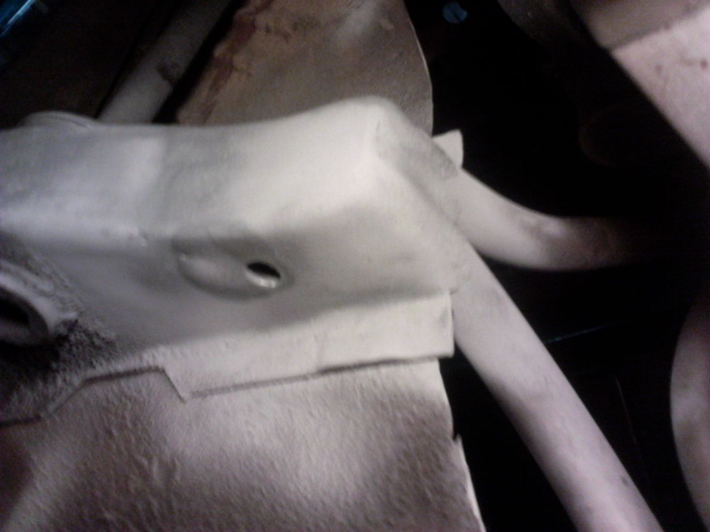
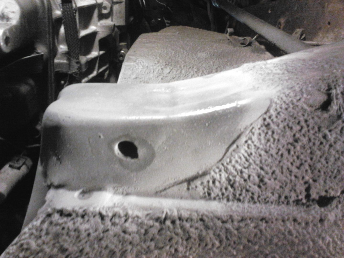
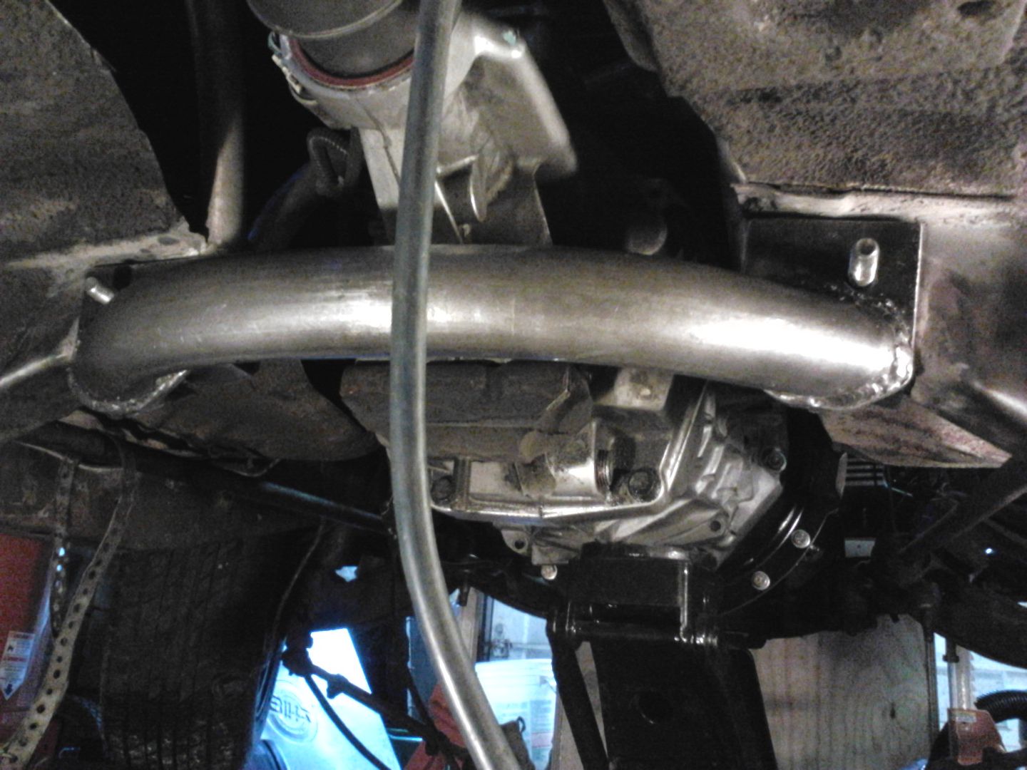
Ok so here we go the first pic is what the frame horns look like with the New peice welded back in and coated with a weld thru primer.


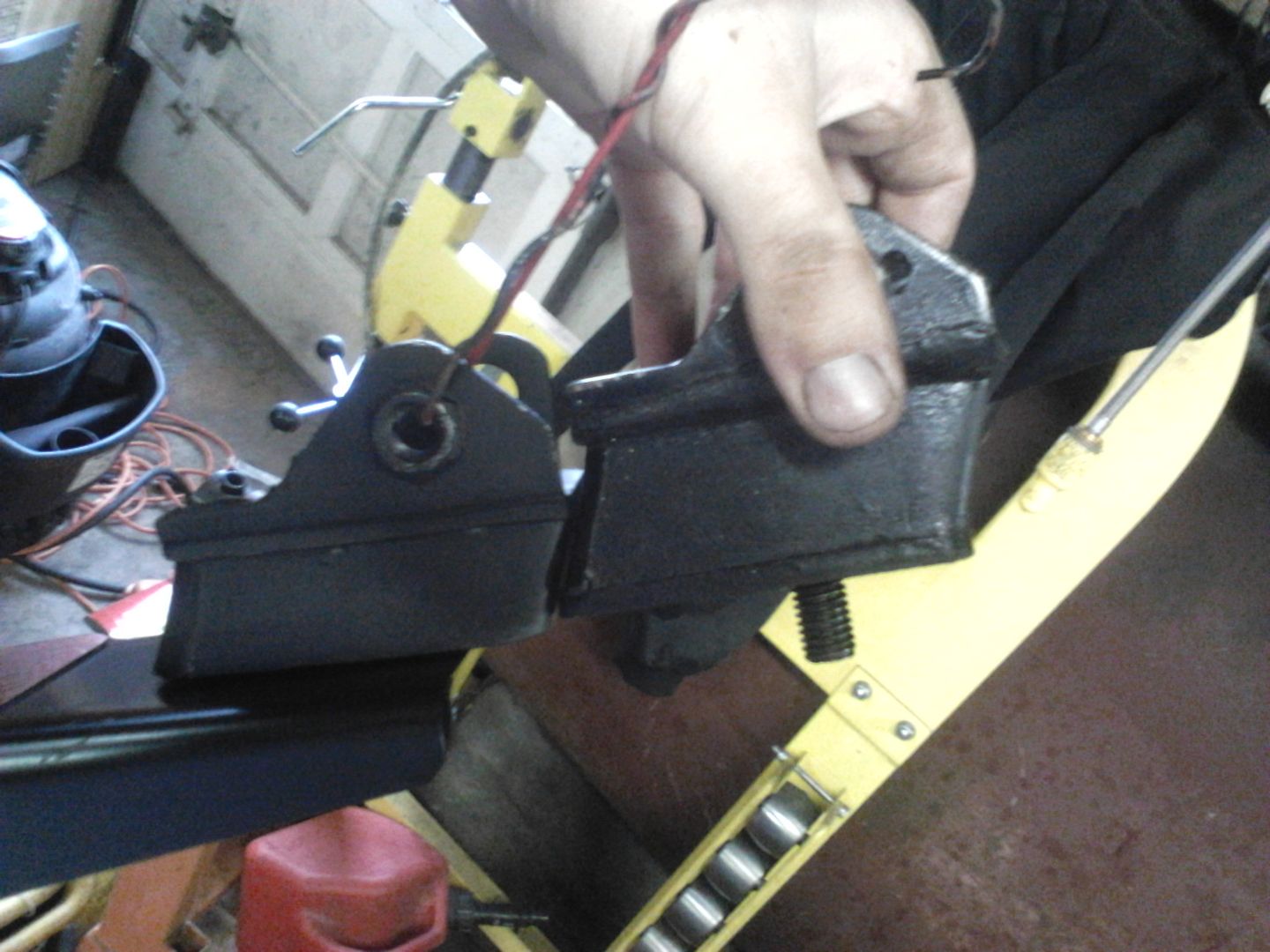
For those who were curious about the engine mount posting earlier...this pick is of the differance in engine mount thickness, the smaller ( and in this case proper) mount is 1.375 thick.
 

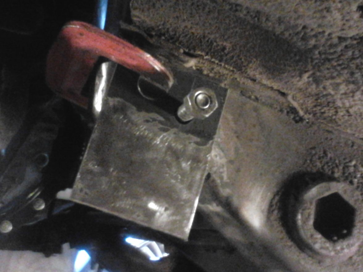
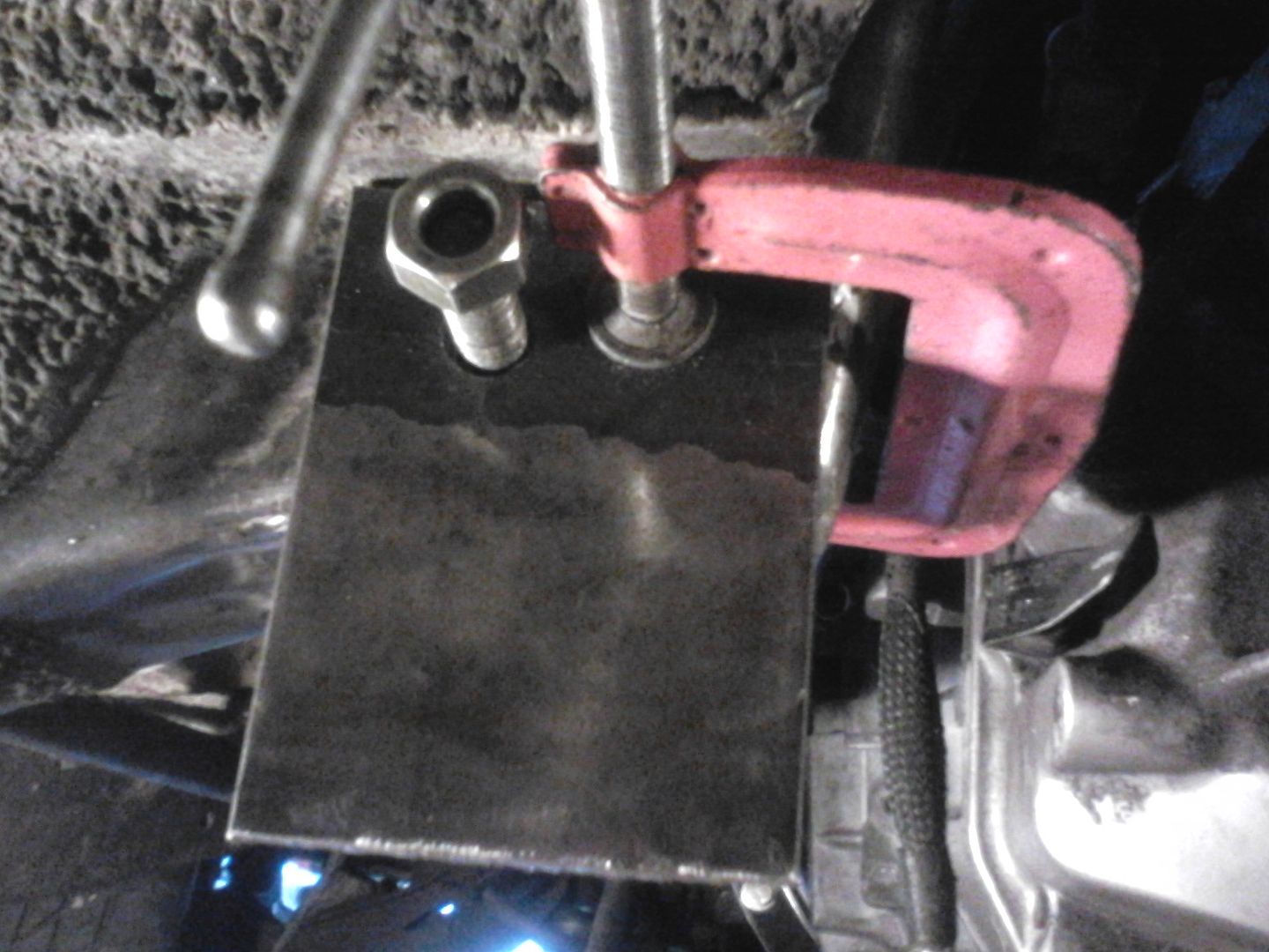
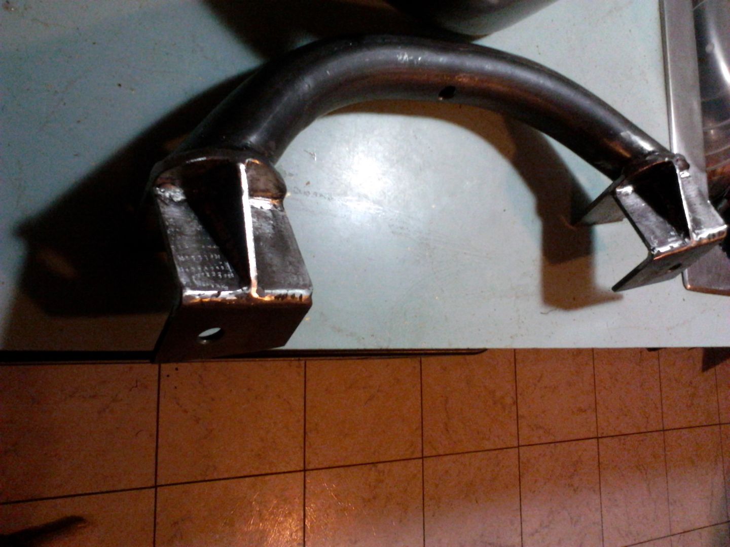
In this photo you can see the start of the trans mounting build.  The material is 3/16 1020 plate which is 2x as thick as the factory steel used here. You will also notice that I am only utilizing 1 bolt per side, the factory uses 4 5/16 shank grade 5 bolts I am using 2 12mm shank grade 10.9 bolts. This set up should be as strong in shear strength as the factory if not better!


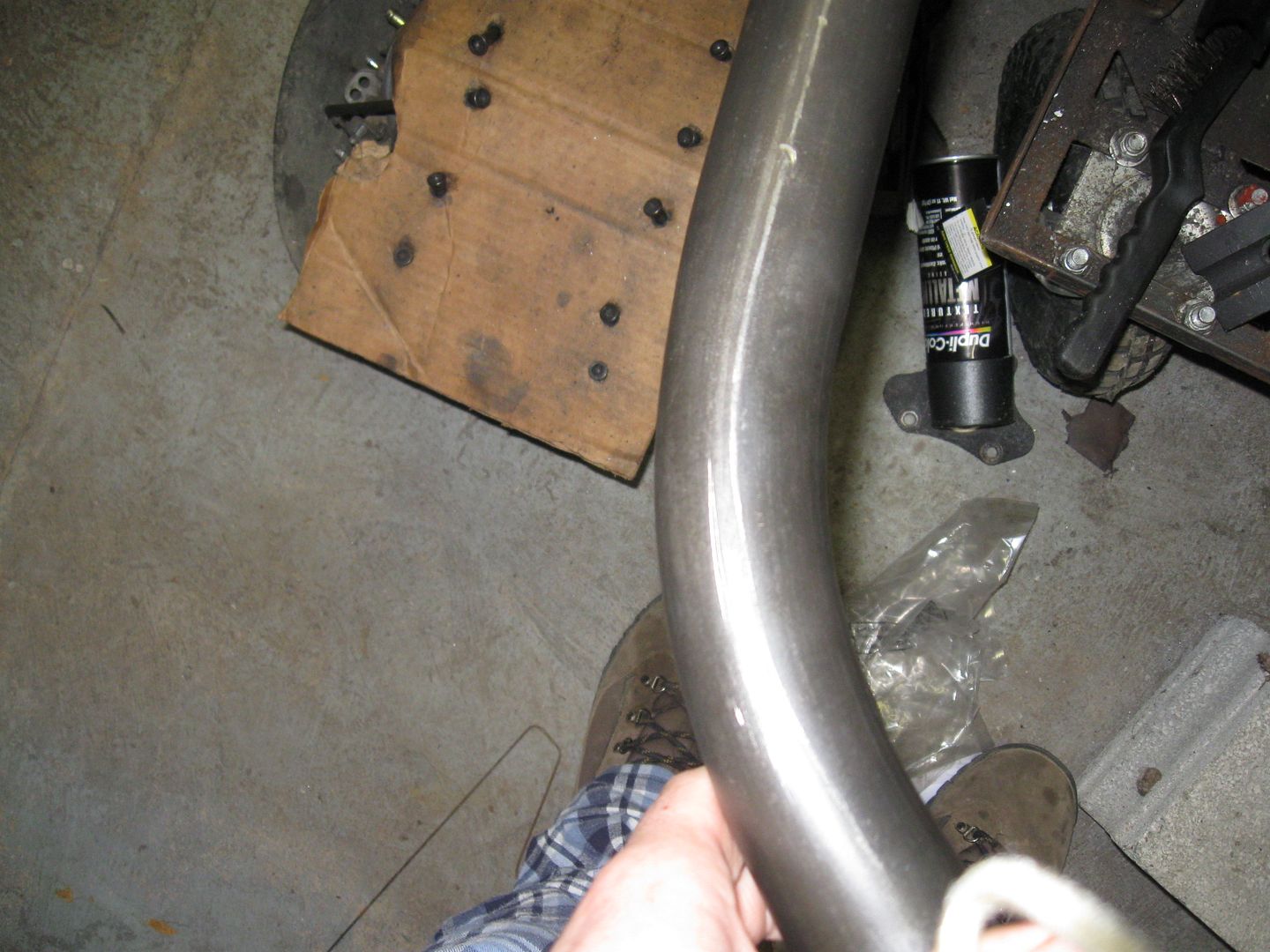
I then bent a piece of 1 3/4 .120 wall 1020 DOM tubing. This actually caused my hydraulic ram on the tubing bender to have a blow out after the first bend was made!
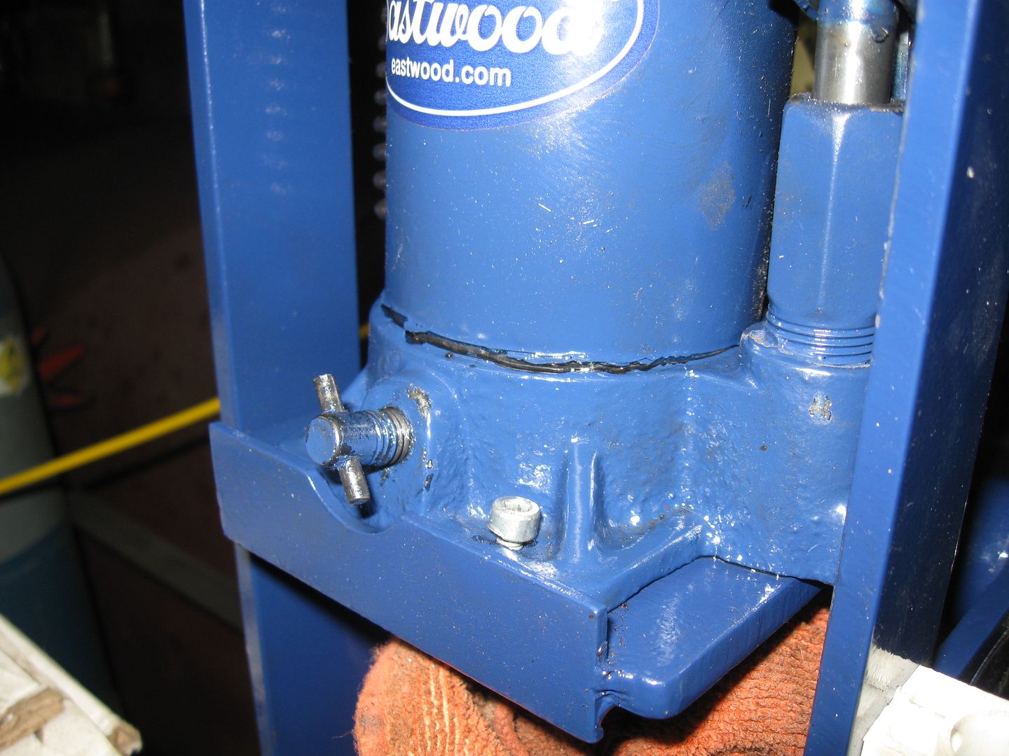


I proptley contacted eastwoods warrenty dep. and got an even heavier duty replacement in about a week for free.  (great company love 'em)
The tubing peice was simply just 2 45 degree bends seperated by a 5 inch flat, then I marked the tubing ends with some masking tape and pie cut them, giving it and overall width of 16 inches. I mocked it up under the car to double check clearances. To weld it in I used 2 scissor jacks and an angle finder to ensure it was level side to side and at the proper hieght.
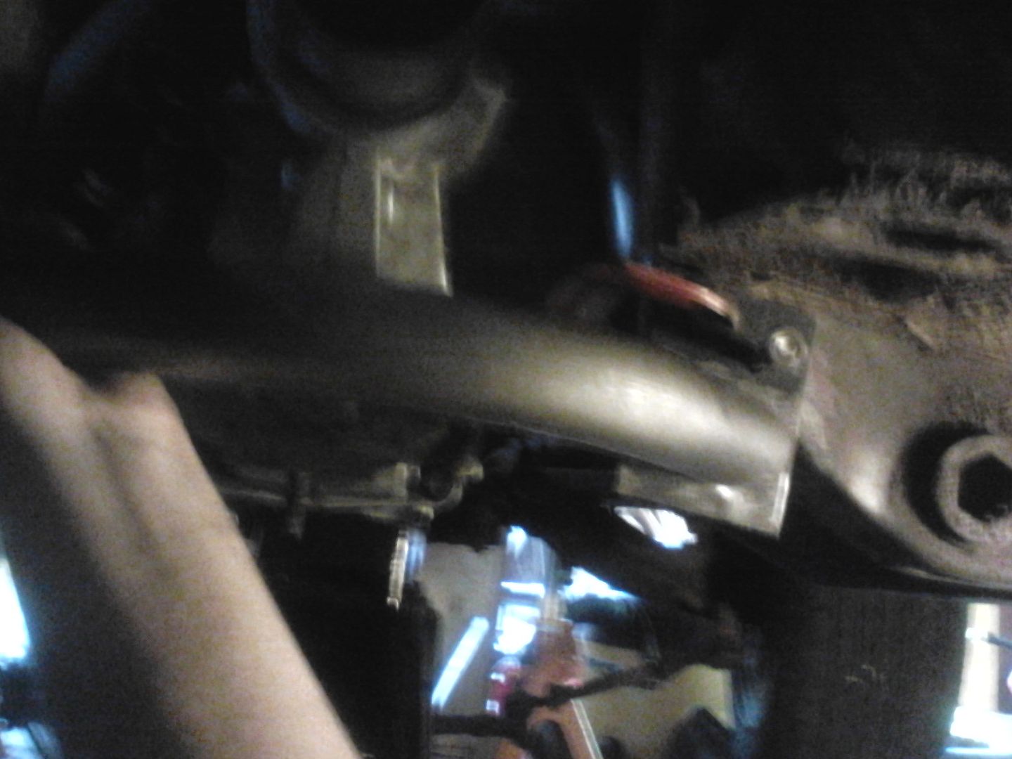


here is an after welding pic


I then made matching caps to go on the opposite side of the frame, and bottom caps, all out of 3/16 plate and welded it. I finished it all up by gusseting it with another piece of 3/16th plate.


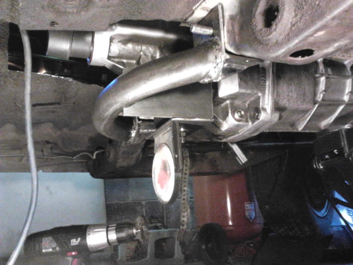
I then started to make the section that would bolt to the trans, the stock viper mount oddly enough is thicker on the passenger side to compensate for torque ( I assume).
So out with the trusty scissor jack and angle finder to preload the bushing for it to sit right. The peice is 5 1/4 x 3 x 3/16 plate steel. The pieces that connect it to the tube are 6 1/4 x 3 x 3/16 plate steel. To make 2 of them more simply I cut a 12 1/2 x 3 piece and used a 1 3/4 inch hole saw on the center line before cuting it in half. I then mocked it up on the car, I knocked off the corners for clearance, using some small welding magnets to help hold and align the pieces as I tack welded it on the car. I removed it and finish welded the piece on my bench. I then metal finished the piece and painted it.
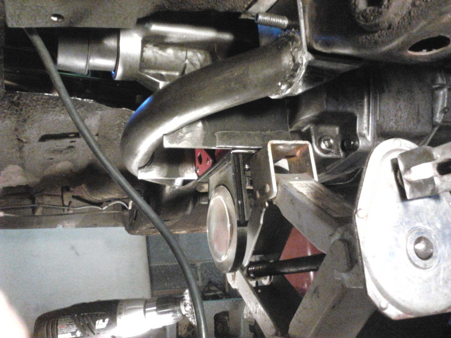
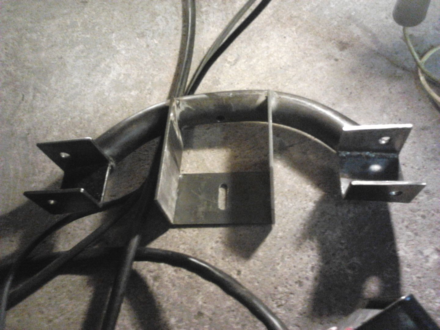
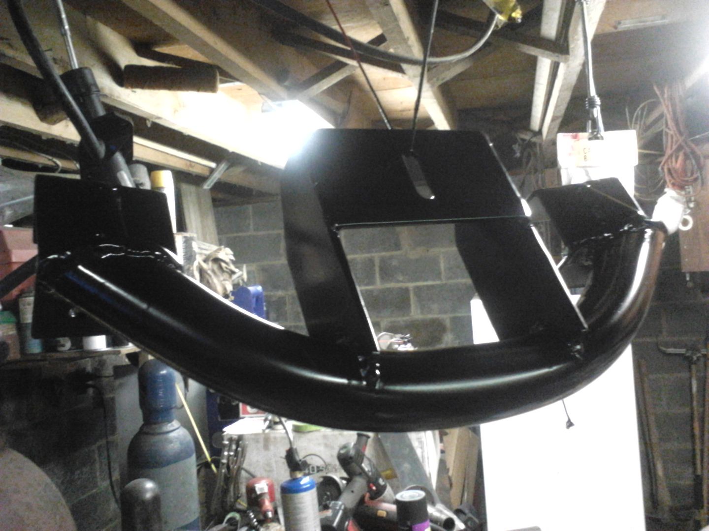


More to come keep your eyes peeled. :working:


Offline 73restomod

  • Full Member
  • ***
  • Posts: 528
Re: Viper 6 speed in a challenger
« Reply #58 on: May 14, 2011 - 04:46:13 PM »
Now on to the fun part sheet metal, hehe, actually it feels really good to be it the home stretch of the fabrication stage!!!! :) Sheet metal work is all about a little knowledge and a lot of patience. I am doing all the sheet metal work with an eastwood 7 peice pro hammer and dolly set, that I bought years ago, then bought again after someone broke into my garage and stole a lot of body work tools and materials... thank god for insurance lol.  I also bought 2 dollies one football shaped and one egg shaped from Harbor Frieght because and only because they were only 5.97 each. In the first 2 pics you can see that I am using some heavy construction paper to make rough templates. the frame will also serve as a faux floor pan.


I am using 18 gauge sheetmetal to remake the FP's. In this next pic you can see the start of the y-shaped section. The shape is roughed out on the piece by hand first (twisting and bending). Then using a clamp as an extra set of hands I hammerformed the piece on the frame itself (carefully). Eventually I had to make 5 relief cuts to get the shape I needed.


Here is the same piece finished and ready for welding. It is actually just sitting there right now it is that well formed. Not tooting my own horn just using it as an example of patience that is required to do sheet metal work right. Granted sometimes you will have to do some of it while the pieces are being welded together too, you can't always get it drop in perfect.


Here is some other pics of the peices as they get finished, the one piece goes on the firewall side of the trans hump.


Well there will be more to post shortly so in the meantime take care all. :working:

Offline 360FISH

  • Full Member
  • ***
  • Posts: 705
  • BS23H3B567746
Re: Viper 6 speed in a challenger
« Reply #59 on: May 14, 2011 - 08:55:45 PM »
amazing!  great skills!
1973 ‘Cuda   Semi-Pro Touring
360 SB - 518/OD auto tranny - FAST EZ EFI - Edelbrock Fuel sump - HHR fan
Hella H4 headlights on relays - 97 Dodge Avenger seats - Chin spoiler - Bumpers pulled in to ’72 offset

Build: http://www.cuda-challenger.com/cc/index.php?topic=74674.0