Use the lowest setting you have. In your case, 200. 3 more clicks counter-clockwise. 
Ok guys I'm finally getting around to wiring this up and I have a few questions...
First when I test resistance to find the high and low beams lug on the bulb, I used the center lug for ground
( correct?) with my meter on the 200 as dodj said to use I get .7 and .8 so the .8 is the low beam correct?
When I touch the leads together I get .5 Did I do this right?
Next question....
Goody, you said to use 12 gauge wire? The relays use 14 gauge and the new headlight sockets are even smaller, should I still use 12 gauge? Newbie here but it seems redundant if what I'm connecting the 12 gauge to is smaller?

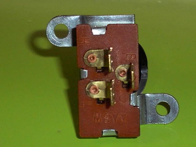
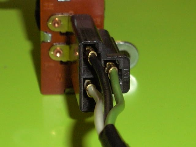
Here is the defroster switch Slotts set me up with, it has 3 prongs , the socket has a white, black and green wire. Do I assume the green is a ground? which other wire do I connect to ( defroster switch) white or black?
next question...
the symbol to the left of the defrost switch in your drawing , that's ground right? Meaning like a wire with an eyelet screwed to the sheetmetal ( body) right?
last question....
in the relay beside the defroster switch 86 just gets connected to 30 correct?
Sorry for the questions but like I said I'm a newbie with wiring.

Thanks for putting up with me guys!