Author Topic: Custom Electrical schematic needed?  (Read 6517 times)

Offline brads70

  • C-C.com Expert
  • ********
  • Posts: 18747
Custom Electrical schematic needed?
« on: October 19, 2010 - 09:55:44 PM »
Hi all!
Let me start off by saying electrical is NOT my strong point. I can follow a drawing, but.....  :icon16:
I was wondering if one of our electrical guru's can make me a drawing I can print off and take to the car with me?
Here is what I want to do,
I have a halo H4 kit. Halo feature wired to running lights. (That's pretty easy)
I have 4 H4 lamps ( 3 prong) 2 of which are yellow that I want to use as running lights that I can switch on and off when I want them? Mounting them in the high beam location. Sort of going for the new Challenger look? If I don't like it I have more clear bulbs.
I have a defogger switch ( 3 position I think?) and harness from member Slotts to use for the yellow lamps.
I have 30 amp relays and fuse holders.
I have  4 new bulb sockets.
I want to build a whole new headlamp harness.
Here is how I want it to work.....
The outboard lamps to function like stock but run through relays.
The inboard ( yellow lamps) also run through relays but using the  defogger switch to turn on the low beam feature and on the second function of the switch to turn on the high beam of the yellow bulbs. Or have it so the foot switch for the high beams turn on all 4 bulbs on high?

I have read Goody's how to on wiring headlights to relays but I really need a drawing for what I want to do so I don't screw up! :grinyes:
HELP?
Brad
1970 Challenger 451stroker/4L60 auto OD
Barrie,Ontario,Canada
Proud to own one of the best cars ever made!!!!!

My restoration thread 
http://www.cuda-challenger.com/cc/index.php?topic=59072.0
 My handling upgrade post
http://www.cuda-challenger.com/cc/index.php?topic=73985.0


Offline GoodysGotaCuda

  • Sr. Resident
  • ******
  • Posts: 5392
Re: Custom Electrical schematic needed?
« Reply #1 on: October 20, 2010 - 08:05:30 AM »
Thinkin on it, I think I can make one for what you are after.

So basically you want the parking lights to work the halos. The low beam yellow will be on it's separate switch (saying it's on the running light circuit, kinda confuses things). The high beam yellow will work with the stock outboard high beams?

Your stock lights on relays yet?
Do you plan on putting them on relays?

May take me a little bit to get the diagram to you, but I can get what you are after...

I'd prefer to just use the stock defroster switch as a ground switch for the relay to work the low beam yellows. Just easier (in my opinion) to do.
Build Page: Goody's 'Cuda Build Page
1976 Dodge Warlock
1972 Barracuda - 5.7 Hemi + T56 Magnum

Wheel & Tire Specs:Link

Offline brads70

  • C-C.com Expert
  • ********
  • Posts: 18747
Re: Custom Electrical schematic needed?
« Reply #2 on: October 20, 2010 - 08:52:59 AM »
Thinkin on it, I think I can make one for what you are after.

So basically you want the parking lights to work the halos. The low beam yellow will be on it's separate switch (saying it's on the running light circuit, kinda confuses things). The high beam yellow will work with the stock outboard high beams?

Your stock lights on relays yet?
Do you plan on putting them on relays?

May take me a little bit to get the diagram to you, but I can get what you are after...

I'd prefer to just use the stock defroster switch as a ground switch for the relay to work the low beam yellows. Just easier (in my opinion) to do.

GREAT! THANKS! :worshippy
Yes I want to put the headlights all on relays ( They are stock wired now) I have 30amp relays to use, is that big enough? Or do I need 40amp+?
Yep I want the halo feature to work with the parking lights.
Yep I'd like the yellow bulbs ( low beam)wired separate to work off the defog switch so I can turn them on and off when I want, low beam on switch, high beam ( all 4 on )when I press the foot switch. So yes to "The high beam yellow will work with the stock outboard high beams"
Thanks! Brad
Brad
1970 Challenger 451stroker/4L60 auto OD
Barrie,Ontario,Canada
Proud to own one of the best cars ever made!!!!!

My restoration thread 
http://www.cuda-challenger.com/cc/index.php?topic=59072.0
 My handling upgrade post
http://www.cuda-challenger.com/cc/index.php?topic=73985.0

Offline GoodysGotaCuda

  • Sr. Resident
  • ******
  • Posts: 5392
Re: Custom Electrical schematic needed?
« Reply #3 on: October 20, 2010 - 12:04:02 PM »
Working on it. I drew it out on paper and need to look it over again and get it to you
Build Page: Goody's 'Cuda Build Page
1976 Dodge Warlock
1972 Barracuda - 5.7 Hemi + T56 Magnum

Wheel & Tire Specs:Link

Offline brads70

  • C-C.com Expert
  • ********
  • Posts: 18747
Re: Custom Electrical schematic needed?
« Reply #4 on: October 20, 2010 - 12:58:30 PM »
Working on it. I drew it out on paper and need to look it over again and get it to you


Wow!!! that's quick! Thanks! :worshippy can you scan it then post it when you have it done? That way I can just print it off? Also someone else down the road might like to do the same and it will then always be here?
Brad
1970 Challenger 451stroker/4L60 auto OD
Barrie,Ontario,Canada
Proud to own one of the best cars ever made!!!!!

My restoration thread 
http://www.cuda-challenger.com/cc/index.php?topic=59072.0
 My handling upgrade post
http://www.cuda-challenger.com/cc/index.php?topic=73985.0

Offline GoodysGotaCuda

  • Sr. Resident
  • ******
  • Posts: 5392
Re: Custom Electrical schematic needed?
« Reply #5 on: October 20, 2010 - 04:38:33 PM »
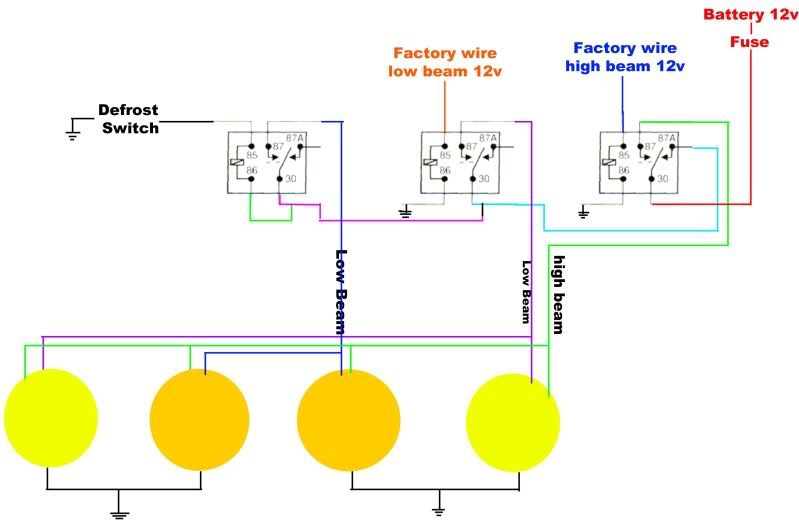
Sorry for the huge diagram! It's extremely basic, but works!


Here is what I have, you will need one FIVE pin relay (still pretty common). 30a should do, but it would be best to post the resistance of your bulb circuits to determine the current draw...That would be both for the relay size and fuse size.

This can look pretty confusing, I'm no electrical engineer, but the noodle in my head says it should work. Now I do not like to run a high and low beam power to a dual filament bulb at the same time for a long period. Which is how your modern car works, if you "flash" your brights the low circuit says energized. If you turn on your high beams the low turns off. I used the painless wiring connectors to the headlights, I'd imagine a parts store would have some basic ones. The high beam circuit needs to have some decent wiring ~12ga (depending on draw) since it will be hitting all four lights on one wire.

Anyway so this is setup to kill power all of the low beam circuits when the highs are kicked on.

I'll try to run through this in a way that can make some sense...

Yellow low beams only

Turn on the stock defroster switch (i do not have a schematic for that, but I have it setup to where you have two wires going to the switch. one ground, and one to the relay)
This grounds out the left control circuit for the relay, switching it.
Power comes from the battery > through the high beam relay > and splits off into the yellow/low relay > power goes out the 87

Low beams, similar to the yellow lows, only the stock low beam wiring controls the relay.

High beams
When the high beams kick on the relay switches power to the low beam circuits to the high beams only (5th pin has power until the relay is switched, killing the low circuits)


this is just how i would do it, I'm no electrical engineer!


« Last Edit: October 20, 2010 - 04:42:04 PM by GoodysGotaCuda »
Build Page: Goody's 'Cuda Build Page
1976 Dodge Warlock
1972 Barracuda - 5.7 Hemi + T56 Magnum

Wheel & Tire Specs:Link

Offline brads70

  • C-C.com Expert
  • ********
  • Posts: 18747
Re: Custom Electrical schematic needed?
« Reply #6 on: October 20, 2010 - 05:05:04 PM »
Here is what I have, you will need one FIVE pin relay (still pretty common). 30a should do, but it would be best to post the resistance of your bulb circuits to determine the current draw...That would be both for the relay size and fuse size.

This can look pretty confusing, I'm no electrical engineer, but the noodle in my head says it should work. Now I do not like to run a high and low beam power to a dual filament bulb at the same time for a long period. Which is how your modern car works, if you "flash" your brights the low circuit says energized. If you turn on your high beams the low turns off. I used the painless wiring connectors to the headlights, I'd imagine a parts store would have some basic ones. The high beam circuit needs to have some decent wiring ~12ga (depending on draw) since it will be hitting all four lights on one wire.


:woohoo: :clapping:  Thanks! That's great! :2thumbs: Perfect just what I needed!
How do I find the resistance of my bulb circuits? With a Ohm meter?  I need to do this first before I start, so I can get the right size relay and fuse size, correct? Sorry I'm electrically Dumb! :grinyes:
Brad
1970 Challenger 451stroker/4L60 auto OD
Barrie,Ontario,Canada
Proud to own one of the best cars ever made!!!!!

My restoration thread 
http://www.cuda-challenger.com/cc/index.php?topic=59072.0
 My handling upgrade post
http://www.cuda-challenger.com/cc/index.php?topic=73985.0

Offline GoodysGotaCuda

  • Sr. Resident
  • ******
  • Posts: 5392
Re: Custom Electrical schematic needed?
« Reply #7 on: October 20, 2010 - 05:32:36 PM »
Yes an ohm meter, preferably not a crazy cheap one. I have a $20 craftsman thats pretty dead on to my snap on multimeter. First check the resistance of the two leads, probably read .2 or something. You will need to subtract that from your reading of the bulb. The ground terminal is the center on the H4, so touch one terminal to center. Then the other and record the readings. The lowest reading will be the high beam circuit and draw more current.
Build Page: Goody's 'Cuda Build Page
1976 Dodge Warlock
1972 Barracuda - 5.7 Hemi + T56 Magnum

Wheel & Tire Specs:Link

Offline brads70

  • C-C.com Expert
  • ********
  • Posts: 18747
Re: Custom Electrical schematic needed?
« Reply #8 on: October 20, 2010 - 05:50:00 PM »
Yes an ohm meter, preferably not a crazy cheap one. I have a $20 craftsman thats pretty dead on to my snap on multimeter. First check the resistance of the two leads, probably read .2 or something. You will need to subtract that from your reading of the bulb. The ground terminal is the center on the H4, so touch one terminal to center. Then the other and record the readings. The lowest reading will be the high beam circuit and draw more current.
Sorry for the questions, like I said I'm electrically dumb! :grinyes:

"resistance of the two leads"   by "leads" do you mean the new plug sockets I have?
I was planning on making a new harness for the wiring up front. I haven't looked to see where it goes to yet? Bulkhead connector?

 With the H4 /9003 bulbs I have they have 3 prongs, 2 parallel and 1 90 degs to the other two. Which one is the ground?
Thanks for your help! :2thumbs:
Brad
1970 Challenger 451stroker/4L60 auto OD
Barrie,Ontario,Canada
Proud to own one of the best cars ever made!!!!!

My restoration thread 
http://www.cuda-challenger.com/cc/index.php?topic=59072.0
 My handling upgrade post
http://www.cuda-challenger.com/cc/index.php?topic=73985.0

Offline dodj

  • Sr. Resident
  • ******
  • Posts: 6197
Re: Custom Electrical schematic needed?
« Reply #9 on: October 20, 2010 - 09:45:06 PM »
Sorry for the questions, like I said I'm electrically dumb! :grinyes:

"resistance of the two leads"   by "leads" do you mean the new plug sockets I have?

He means the resistance of the two testing 'leads' from the meter.
I don't remember which prong is ground but it is the black wire on original harness.
Scott
1973 Challenger  440 4 spd 
2007.5 3500 6.7 Cummins Diesel, Anarchy tuned.
Good friends don't let friends do stupid things. ........alone.

Offline brads70

  • C-C.com Expert
  • ********
  • Posts: 18747
Re: Custom Electrical schematic needed?
« Reply #10 on: October 20, 2010 - 10:50:46 PM »
He means the resistance of the two testing 'leads' from the meter.
I don't remember which prong is ground but it is the black wire on original harness.
Ah that makes scence! :banghead: :smilielol: Thanks!
Brad
1970 Challenger 451stroker/4L60 auto OD
Barrie,Ontario,Canada
Proud to own one of the best cars ever made!!!!!

My restoration thread 
http://www.cuda-challenger.com/cc/index.php?topic=59072.0
 My handling upgrade post
http://www.cuda-challenger.com/cc/index.php?topic=73985.0

Offline GoodysGotaCuda

  • Sr. Resident
  • ******
  • Posts: 5392
Re: Custom Electrical schematic needed?
« Reply #11 on: October 21, 2010 - 09:46:22 AM »
Ground on the light should be the 'middle' terminal. You can check for sure when you do your resistance setting. It is the only terminal that is in common with the other two.

Hope the diagram helps, in my head it'll work  :eek4:
Build Page: Goody's 'Cuda Build Page
1976 Dodge Warlock
1972 Barracuda - 5.7 Hemi + T56 Magnum

Wheel & Tire Specs:Link

Offline brads70

  • C-C.com Expert
  • ********
  • Posts: 18747
Re: Custom Electrical schematic needed?
« Reply #12 on: October 21, 2010 - 06:46:26 PM »
Ok what setting do I select to check the resistance of the bulbs? :newbie: :bigsmile:
Hope this meter is good enough?


Ok while on the 200 reading I got .7 as the highest reading( yellow bulbs 1.2) that's subtracting the reading while touching the leads together(.5).
So how do I from that tell what size fuses,wire gauge , and relay size do I need?
I'm learning something here! :clapping: :2thumbs:
« Last Edit: October 21, 2010 - 09:54:16 PM by brads70 »
Brad
1970 Challenger 451stroker/4L60 auto OD
Barrie,Ontario,Canada
Proud to own one of the best cars ever made!!!!!

My restoration thread 
http://www.cuda-challenger.com/cc/index.php?topic=59072.0
 My handling upgrade post
http://www.cuda-challenger.com/cc/index.php?topic=73985.0

Offline dodj

  • Sr. Resident
  • ******
  • Posts: 6197
Re: Custom Electrical schematic needed?
« Reply #13 on: October 21, 2010 - 07:21:47 PM »
Use the lowest setting you have. In your case, 200. 3 more clicks counter-clockwise. :2thumbs:
Scott
1973 Challenger  440 4 spd 
2007.5 3500 6.7 Cummins Diesel, Anarchy tuned.
Good friends don't let friends do stupid things. ........alone.

Offline dodj

  • Sr. Resident
  • ******
  • Posts: 6197
Re: Custom Electrical schematic needed?
« Reply #14 on: October 21, 2010 - 07:35:37 PM »
Hope the diagram helps, in my head it'll work  :eek4:
Works in my head too. Just nitpicking, but I'd rather switch power than ground for the left-most relay, but it'll work fine either way. I'd put the defrost sw. between 30 and 86 and tie 85 to gnd. :2cents:
Scott
1973 Challenger  440 4 spd 
2007.5 3500 6.7 Cummins Diesel, Anarchy tuned.
Good friends don't let friends do stupid things. ........alone.